Arduino Tutorial: Lesson 3 - Breadboard and LEDs
This tutorial is by Limor Fried and from http://www.ladyada.net/learn/arduinoIntroduction
You've started modifying sketches, and played a bit with the onboard LED (or if you have an NG, an LED you added). The next step is to start adding onto the hardware component of the Arduino. We will do this by adding a solderless breadboard to our setup, connecting up new parts with wire.
Get your gear
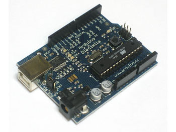
Assembled Arduino board, preferrably a Diecimila
(or whatever the latest version is) but NG is OK too
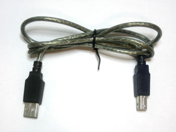
USB Cable. Standard A-B cable is required. Any length is OK.
LEDs: For this lesson, a red, green and blue LED are best. Make sure you get a "5mm" or "3mm" LED, with two legs, as shown in the example image. "Ultrabright" LEDs (1000 mcd rating or higher) are preferred

Any values from 300 Ω to 2KΩ are probably OK.
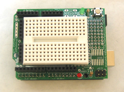
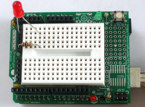
Arduino Prototyping Shield with tiny breadboard
Standard solderless breadboard - If you don't have a protoshield,
this is a substitute

Say hello to the solderless breadboard!
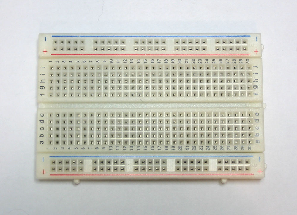
Solderless breadboards are an important tool in your quest for electronics mastery. They allow you to make quick circuits, test out ideas before making a more permanent Printed Circuit Board. They're also inexpensive and reusable.. You can pick on up at any hobby shop or electronics supply store. They often look like this
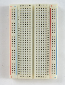
Basically, a chunk of plastic with a bunch of holes. However, something special is going on inside the breadboard! Although you can't see it, inside the breadboard are many strips of metal that connect the rows and columns together. The metal strips are springy so that when you poke a wire into the hole, the clips grab onto it.
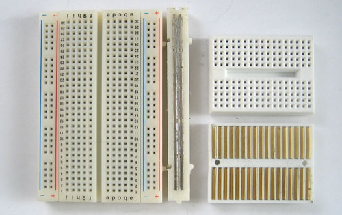
In the images above you can see how there are two kinds of metal strips. There are short ones that connect 5 row holes at a time, and then there are very long ones that connect 25 (or more!) column holes at a time. The long columns are called rails and the short strips are called rows. Breadboards are almost always made so that they have two sets of 5-hole rows and on either side there are a pair of rails. For example the breadboard on the left has 30 row pairs and 2 sets of double rails on either side. The one on the right is quite small, it has only 17 row pairs and no rails.
In this lesson, we will show pictures of both the tiny breadboard on a protoshield and also using a 'standard' breadboard without a shield. However, after this lesson, you'll be more on your own to figure out how to connect up the standard breadboard, OK?
Warning!
Distressing as it may sound, solderless breadboards can be very flakey, especially as they age. If you're having problems with your circuit, it could be that the little metal clips on the inside aren't working well. Try poking it with your finger, or moving it to a different section.
Say hello to wires!
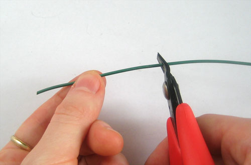
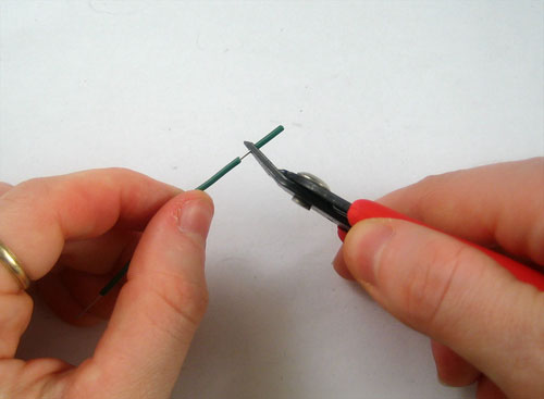
To use the breadboard, you'll need jumper wires. These are basically 22 gauge solid-core (not stranded) wires that are cut down and have the insulation pulled off. You can use a fingernail or, best of all, a real wirestripper tool to remove the insulation, just takes a few tries and then its really easy.
Heres how to do it with just diagonal cutters ... Cut the wire first, using wire cutters
Nick the insulation, then pull it off.
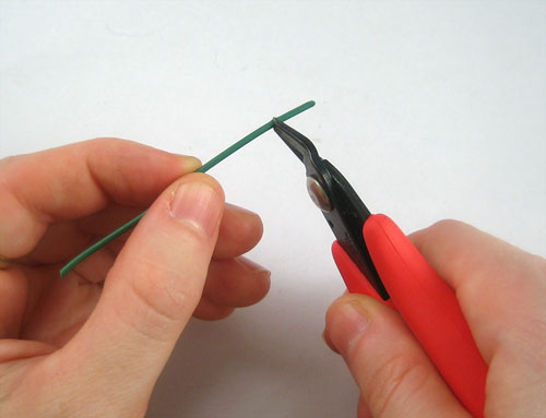
To connect rows together, just stick the wire ends without insulation into the square holes!
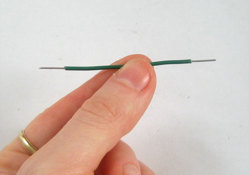
Now is a good time to practice making jumpers, go forth and make a few 3" long jumpers!
Say hello to the resistor!
The resistor is the most basic and also most common electronic part. An electronic gadget, such as an mp3 player has easily a thousand resistors inside of it!
One common way of thinking about this is if we were talking about water current, then pipes are like resistors. Thin pipes let less water through (high resistance), thick pipes let a lot of water through (low resistance). Wth a fire hydrant, you want low resistance. With a water fountain, you'd want high resistance. If you mixed up the two pipe sizes, you wouldnt be able to put out a fire and you'd hurt yourself while trying to get a drink.
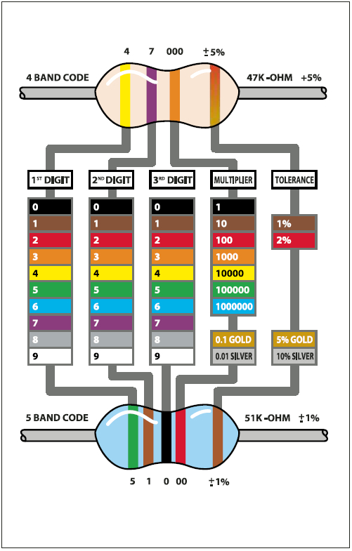
Resistance is measured in ohms, often written as the symbol Ω. The bigger the resistance value (in ohms) the more it fights. Most resistors you'll see range between 1 ohm and 1 megaohm (1.0 MΩ). Since the resistive element is inside a ceramic casing, its not possible to tell the resistance of a resistor just by looking at it. You'll have to read it by looking at the colored stripes on the body of the resistor. This is known as the resistor color code, and its a real pain when you first start electronics. Eventually you'll get really good at telling the value of a resistor just by glance but to start off you'll want to use a reference chart. (Or you can use a multimeter to measure the resistance accurately)
View a reference chart
Quick quiz!
What is the colour code for a 5% 1.0KΩ resistor? (Highlight the text below to see the answer)
Brown - Black - Red - Gold
What is the color code for a 5% 220Ω resistor? (Highlight the text below to see the answer)
Red - Red - Brown - Gold
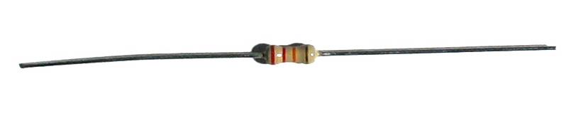
What is the value of this resistor? (Highlight the text below the picture to see the answer)

What happens if you put a resistor in backwards? (Highlight the text below to see the answer)
Ha! Trick question, it is not possible to put a resistor in 'backwards'. They work either way!
Note on Wattage ...
In all these examples, we use 1/4W resistors. Unless otherwise noted you can use 1/16 W or 1/2W or whatever you can get your hands on. Higher wattage resistors are larger and usually more expensive, but sometimes your local hobby shop will only have 1/2W.
Say hello to the LED!
We've had some time with the LED already, but lets get to know her a little better. The word LED stands for Light Emitting Diode. The light-emitting part, well, that makes sense. We've used the LED to make a blinking light in lessons 1 and 2. The LED component turns current into light, much like any sort of light bulb. But what is this mysterious diode?
A diode is basically a one-way street for current. Imagine such a one-way street with a traffic policeman in front. If you want to turn onto the street the wrong way, he will not let you. Likewise the diode simply does not let current go through it the wrong way. Current in a diode can only flow from the positive side to the negative side.
If you recall from lesson 1, Arduino NG users had to make sure that they inserted the LED in the right way. If you place the LED in backwards it won't work. Diecimila Arduino users already have the LED (a very very small one) soldered onto the circuit board the right way.
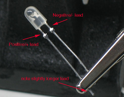
As we mentioned before, its easy to figure out which side of an LED is positive and which one is negative. The positive leg is slightly longer and if you look inside, the chunk of metal is larger on the negaive side.
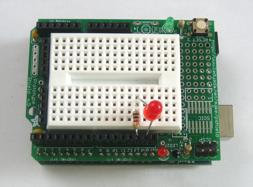
Light up my breadboard
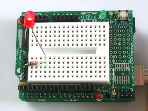
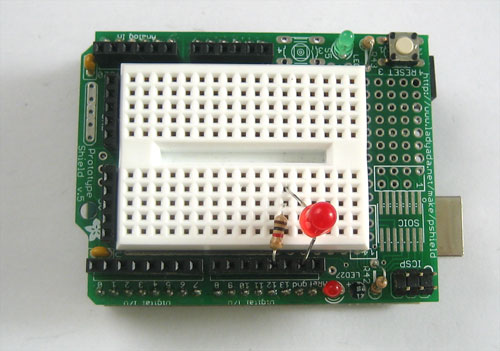
We're going to now use the breadboard to light up an LED. You will need a breadboard, an LED and a 1.0K ohm resistor (brown black red gold). If you have a protoshield, make sure its assembled first. Then, place the tiny breadboard on top. You can remove the backing to stick it on (which is permanent) or you can just use double-sided tape. If you have a regular breadboard you'll need 2 jumper wires as well.
Important Note!
While LEDs will not work when placed backwards, you don't have to worry about whether it will be damaged: as long as there is a series resistor of at least 100 ohms next to it, the LED will survive the experience!
However, using an LED without a series resistor is a sure-fire way to kill it! (You'll see a bright flash and it may turn dark).
Always use a resistor! A 1.0K ohm is a good place to start. We'll cover how to figure out the best resistor value later on.
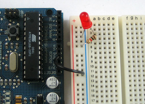
Place the resistor and LED as shown. Make sure the longer leg of the LED is to the right, connected to the resistor. The resistor doesn't have a direction, so it doesn't matter which way it goes in.
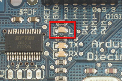
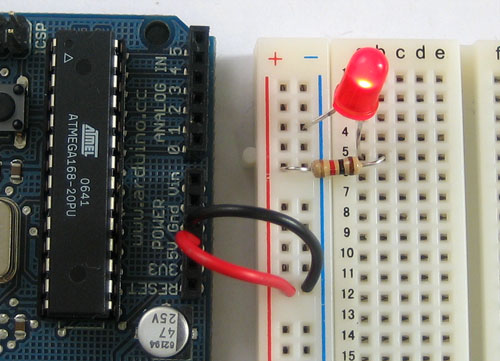
If you're using a standard breadboard, you'll need to use wires to reach the Arduino. Run one wire (red) to the 5V socket on the Arduino. Run the other wire (black) to one of the GND sockets on the Arduino. The colors aren't essential but they will help you remember what the wires are connected to!
Plug in the Arduino, you should see the LED light up. If not, check the following:
- Is the Arduino plugged in? (look for the little green light on the Arduino as in lesson 0)
- Is the LED in backwards? Try flipping it around, just in case. This wont damage the LED.
- Are the parts firmly placed in the breadboard? Loose parts are a common breadboard problem, try jiggling them with a finger and see if it starts working.
- Is the LED on and its just very dim? Try turning down the lights or looking at it head on: some LEDs are very directional.
- Is the red wire going into the hole labeled 5V? Is the black wire going into one of the holes labeled GND?
Make sure the parts are as shown in the image above, if you have a wire in one row and the resistor in the other, they aren't connected and it wont work!
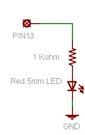
Scheming schematic
Hooray, you just built your first circuit! It's quite simple but still worth explaining.
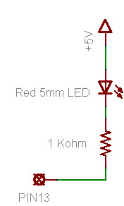
Basically you've connected the LED and resistor in series (one after the other) to a 5V 'battery'. The positive pin of the LED is connected to the positive terminal of the battery, then the negative pin is connected to a resistor which goes to the negative terminal of the battery. The battery is supplying the current that flows through the LED, making it light up.
The positive and negative battey terminals are often called the power supply, as they supply power to our circuit. The positive terminal is called power (as thats where current flows from) and the negative terminal is called ground, as it is where current flows to.
Lets say you want to "save" this design and send it to a friend to check out and build for herself...one way you could do that is to take a good photo. But a better way is to draw a wiring diagram. Then it wouldn't matter if your camera wasn't very good. A wiring diagram is also known as a schematic. Schematics are the standard method for people to trade information about circuits. Being able to read and write schematics is a key skill! Here is a schematic for a really big project, a Roland TB-303 synthesizer clone
Each electronic component has a schematic symbol, which is a simplified drawing of the part. For resistors the symbol looks like this:

Resistor symbol
And the symbol for LED's look like this:

LED symbol, positive pin on the left, negative pin on the right
You can see that the resistor symbol is symmetric, just like resistors themselves. The LED symbol, however, has an arrow thing going on. This is the direction in which current flows. The little arrows that are coming out of the symbol indicate that this is a diode that emits light.
Power and ground also have symbols:
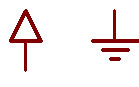
Power and Ground symbols
The only thing we need to do now is indicate how the LED and resistor are hooked up and show the 5V and ground connections.
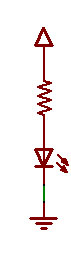
A barebones schematic
Next to symbols, we often write important information like what the resistor value is, what color and size the LED should be, and the voltage associated with the power supply.
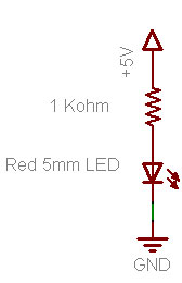
A well documented schematic!
For practice, try drawing your own schematic on a piece of paper.
A Quick Rewiring ...
We're going to make a very small modification to our wired up circuit
Before you change your breadboard, make a guess of what will happen:
- Will the LED stay lit?
- Will the LED go out?
- Something else?
Now make the change to your breadboard:
You will notice that, in fact, the LED has gone out. That is because it is no longer connected to a power source and current is not flowing. By connecting the resistor to +5V or ground, you can turn the LED on and off. If you were very fast at it, you could make the LED blink!
Hmm....
Re-visiting an old friend
Start up the Arduino software again and open up the MyBlink sketch from lesson 2. If you left it with delay times of 10ms, you may want to modify it so its back to 500ms on and 500ms off. Upload the sketch to your Arduino. Now change your breadboard wiring so that it matches this schematic.
void loop()                     // run over and over again
{
  digitalWrite(ledPin, HIGH);   // sets the LED on
  delay(500);                  // waits for a second
  digitalWrite(ledPin, LOW);    // sets the LED off
  delay(500);                  // waits for a second
}
We didn't quite explain what digitalWrite does, but now it should be clear: the digitalWrite procedure connects the pin indicated by the first input (ledPin) to either the +5V power supply or to ground depending on the second input (HIGH or LOW)
This is a pretty awesome capability and is the basis of all electronics! You may want to think about how cool it is for a few moments.
A new pin
Now change the wiring so that the resistor is connected up to pin socket #12


The LED isn't be blinking anymore! Lets fix it!
Go back to the beginning of the sketch and find this line again
int ledPin = 13; // LED connected to digital pin 13
int ledPin = 12; // LED connected to digital pin 12 now!
Exercises!
Spend some time experimenting with different pins. Connect the LED to different pin sockets, and modify the sketch so that the LED blinks.
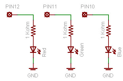
Change around your wiring so that it matches this schematic:
Make sure to modify you sketch so that the ledPin is 13 again. Re-compile and upload it to the Arduino. What does the LED do? (Highlight the text below to see the answer)
It blinks just like beforeIf you have a Diecimila Arduino, what do you notice about the breadboard LED and the on-board LED? (Highlight the text below to see the answer)
They are alternating when they blink
Why do you think that is? (Highlight the text below to see the answer)
When the pin is LOW (connected to ground) the breadboard LED is on: current is flowing from +5V to ground through the pin. When the pin is HIGH (connected to +5V) the on-board LED is on, just like before.
Adding a green LED ...
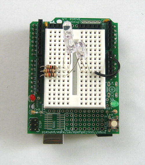
OK sure you've had plenty of practice messing around with LEDs. It's time to go full color! Find a red, green and blue LED. If you have the Arduino Starter Pack they will be the three clear LEDs. You can't tell which one is which until they are lit so just build the circuit and then rearrange them if needed.
Go back to your sketch and change it so it looks like this:
int redPin = 12;                  // Red LED connected to digital pin 12
int greenPin = 11;                // Green LED connected to digital pin 11

void setup()                      // run once, when the sketch starts
{
  pinMode(redPin, OUTPUT);        // sets the digital pin as output
  pinMode(greenPin, OUTPUT);      // sets the digital pin as output
}

void loop()                       // run over and over again
{
  digitalWrite(redPin, HIGH);     // sets the Red LED on
  digitalWrite(greenPin, HIGH);   // sets the Green LED on
  delay(500);                     // waits for half a second
  digitalWrite(redPin, LOW);      // sets the Red LED off
  digitalWrite(greenPin, LOW);    // sets the Green LED off
  delay(500);                     // waits for half a second
}
You can just copy and paste this text into your Arduino software window.
Quick quiz
What does this sketch do? Compile and upload the sketch to test your hypothesis. Highlight the text below to see the answer
It blinks the two LEDs connected to pins 11 and 12 at the same time
3434343434
If you are having problems getting this sketch to work, double check:
Is the sketch compiling properly? Did it upload correctly?
Are the LEDs in the right way?
Are the resistors in the right sockets?
Are the LEDs connected to ground on the other side?
Is the breadboard wired up right? Check your connections.
Exercises!
Change the code so that the LEDs alternate their blinks:
3535353535
Highlight the text below to see one possible solution
Change the second digitalWrite() procedure call to set the pin LOW, and the fourth call to set the pin HIGH.
Change the loop() procedure code so that both LEDs are on for 500 ms, then only the red LED is on for 500 ms, then both LEDs are off, and finally only the green LED is on for 500 ms. (Highlight the text below to see the answer)
void loop() // run over and over again
{
digitalWrite(redPin, HIGH); // sets the Red LED on
digitalWrite(greenPin, HIGH); // sets the Green LED on
delay(500); // waits for half a second
digitalWrite(redPin, HIGH); // sets the Red LED on
digitalWrite(greenPin, LOW); // sets the Green LED off
delay(500); // waits for half a second
digitalWrite(redPin, LOW); // sets the Red LED off
digitalWrite(greenPin, LOW); // sets the Green LED off
delay(500); // waits for half a second
digitalWrite(redPin, LOW); // sets the Red LED off
digitalWrite(greenPin, HIGH); // sets the Green LED on
delay(500); // waits for half a second
}
Full color adventures!
After successfully adding support for the green LED its time to add in the blue LED.
Go back to this sketch, the one from the last step
int redPin = 12; // Red LED connected to digital pin 12
int greenPin = 11; // Green LED connected to digital pin 11
void setup() // run once, when the sketch starts
{
pinMode(redPin, OUTPUT); // sets the digital pin as output
pinMode(greenPin, OUTPUT); // sets the digital pin as output
}
void loop() // run over and over again
{
digitalWrite(redPin, HIGH); // sets the Red LED on
digitalWrite(greenPin, HIGH); // sets the Green LED on
delay(500); // waits for half a second
digitalWrite(redPin, LOW); // sets the Red LED off
digitalWrite(greenPin, LOW); // sets the Green LED off
delay(500); // waits for half a second
}
You can just copy and paste this text into your Arduino software window.
Now you will add the code for the Blue LED by yourself
Step 1. Add the line of code that will create a variable called bluePin. What pin should it be assigned? Examine the schematic above to find out.
Step 2. Add the line of code that will tell the Arduino that bluePin is a digital output.
Step 3. Add the 2 lines of code so that the blue LED will be lit when the red and green LEDs are lit
Compile and verify your code. Does it work? If not use your debugging skills to figure out what is wrong and fix it!
Color mixing
Now that you have red, green and blue light, you can start having fun with color mixing. Color mixing is the neat ability that our eyes have to combine different light colors and create a new color
3636363636
A additive (light) color mixing diagram
According to this diagram, if we have both red and blue light mixed together we should get a violet light.
Quick quiz
Modify your code to create the following colored light: Violet (red & blue), Turquoise (blue & green) and yellow (green & red)
Now you are ready for the "final project" of this very long lesson. You are going to make a color changing light!
Modify the sketch so that the emitted light goes in order: red, yellow, green, turquioise, blue violet and back to red. It should pause about half a second between each color change.
Hint: One way to make the color mixing work better is to diffuse the light, in a light box. You can make a light box out of plain paper, scissors and some tape. Just make a paper box and cut a hole in it. Fill the box with tissue paper. The tissue acts as a diffuser, helping the light mix nicely
3737373737
3838383838
3939393939
Arduino Hướng dẫn: Bài 3 - breadboard và đèn LED
Giới thiệu
Bạn đã bắt đầu thay đổi bản phác thảo, và chơi một chút với các đèn LED trên máy bay (hoặc nếu bạn có một NG, một đèn LED bạn đã thêm vào). Bước tiếp theo là để bắt đầu thêm vào các thành phần phần cứng của Arduino. Chúng tôi sẽ làm điều này bằng cách thêm một breadboard solderless để thiết lập của chúng tôi, kết nối các bộ phận mới với dây.
Bánh của bạn
Lắp ráp Arduino hội đồng quản trị, Ưu tiên sử Diecimila (hoặc bất cứ phiên bản mới nhất) nhưng NG là OK
Cáp USB. Tiêu chuẩn cáp A-B được yêu cầu. Chiều dài bất kỳ là OK.
Đèn LED: Đối với bài học này, một màu đỏ, xanh lá cây và màu xanh LED là tốt nhất. Hãy chắc chắn rằng bạn nhận được một "5mm" hoặc "3mm" LED, với hai chân, như thể hiện trong hình ảnh ví dụ. "Ultrabright" LED (1000 mcd đánh giá hoặc cao hơn) được ưa thích
1KΩ điện trở (nâu đen đỏ vàng)
Bất kỳ giá trị từ 300 Ω để 2KΩ có thể OK.
Arduino Prototyping Shield với breadboard nhỏ
Standard solderless breadboard
Nếu bạn không có một protoshield, điều này là một thay thế
Khô kết hợp Wire. 22 gauge rắn lõi dây màu đỏ, đen và màu sắc khác. Hãy chắc chắn rằng dây của nó không bị mắc kẹt!
Breadboard solderless!
Solderless breadboards là một công cụ quan trọng trong việc tìm kiếm của bạn cho thiết bị điện tử chủ. Chúng cho phép bạn để làm cho mạch nhanh chóng, thử nghiệm những ý tưởng trước khi đưa ra Hội đồng mạch in lâu dài hơn. Chúng tôi cũng không tốn kém và có thể tái sử dụng .. Bạn có thể chọn tại bất kỳ cửa hàng sở thích hoặc cửa hàng cung cấp thiết bị điện tử. Họ thường nhìn như thế này
Về cơ bản, một đoạn nhựa với một loạt các lỗ. Tuy nhiên, một cái gì đó đặc biệt đang xảy ra bên trong breadboard! Mặc dù bạn không thể nhìn thấy nó, bên trong breadboard là dải kim loại kết nối các hàng và cột lại với nhau. Dải kim loại đàn hồi để khi bạn chọc một sợi dây vào lỗ, clip bám vào nó.
Trong những hình ảnh trên, bạn có thể thấy có hai loại dải kim loại. Có những người ngắn kết nối 5 lỗ hàng tại một thời điểm, và sau đó có những người rất dài kết nối 25 (hoặc nhiều) lỗ cột tại một thời điểm. Các cột dài được gọi là đường ray và các dải ngắn được gọi là các hàng. Breadboards được hầu như luôn luôn được thực hiện để họ có hai bộ hàng 5 lỗ và hai bên có là một cặp đường ray. Ví dụ breadboard bên trái có 30 cặp hàng và 2 bộ đường ray đôi hai bên. Một bên phải khá nhỏ, chỉ có 17 cặp hàng và không có đường ray.
Trong bài học này, chúng tôi sẽ hiển thị hình ảnh của breadboard cả hai nhỏ trên protoshield và cũng bằng cách sử dụng một breadboard 'tiêu chuẩn' mà không có một lá chắn. Tuy nhiên, sau bài học này, bạn sẽ được thêm vào của riêng bạn để tìm ra cách để kết nối các breadboard tiêu chuẩn, OK?
Cảnh báo!
Đau khổ vì nó có thể âm thanh, solderless breadboards có thể là rất flakey, đặc biệt là khi có tuổi. Nếu bạn gặp vấn đề với mạch của bạn, nó có thể là các clip kim loại nhỏ bên trong không làm việc tốt. Hãy thử chọc nó với ngón tay của bạn, hoặc di chuyển nó đến một phần khác nhau.
Để sử dụng breadboard, bạn sẽ cần nhảy dây. Đây là những cơ bản 22 gauge lõi rắn (không bị mắc kẹt) dây được cắt giảm và có cách điện kéo. Bạn có thể sử dụng móng tay, tốt nhất của tất cả các wirestripper một công cụ thực để loại bỏ các vật liệu cách nhiệt, chỉ mất một vài cố gắng và sau đó thực sự của nó dễ dàng.
Heres làm thế nào để làm điều đó với máy cắt chỉ đường chéo ... Cắt dây đầu tiên, bằng cách sử dụng máy cắt dây
Nick cách điện, sau đó kéo nó ra khỏi.
Để kết nối các hàng với nhau, chỉ dính dây kết thúc mà không có cách nhiệt vào các lỗ vuông!
Bây giờ là thời điểm tốt để luyện tập nhảy, đi ra và làm cho 3 vài "nhảy dài!
Điện trở!
Điện trở là một phần điện tử cơ bản nhất và cũng phổ biến nhất. Một tiện ích điện tử, chẳng hạn như một máy nghe nhạc mp3 có dễ dàng một ngàn điện trở bên trong của nó!
Điện trở có một công việc để làm, và đó là để chống lại dòng chảy của điện (nếu không được biết đến như hiện nay). Đó là lý do tại sao họ được gọi là điện trở. Chống lại hiện tại mà họ kiểm soát ở đâu và làm thế nào nhanh chóng nó chảy.
Một trong những cách phổ biến suy nghĩ về điều này là nếu chúng ta đang nói về nước hiện nay, sau đó dẫn như điện trở. Ống mỏng để nước qua (sức đề kháng cao), ống dày cho rất nhiều nước thông qua (sức đề kháng thấp). Wth 1 trụ nước cứu hoả, bạn muốn trở kháng thấp. Với một đài phun nước, bạn sẽ muốn có sức đề kháng cao. Nếu bạn trộn lẫn hai đường ống kích cỡ, bạn wouldnt có thể đặt ra một đám cháy và bạn muốn làm tổn thương chính mình trong khi cố gắng để có được một thức uống.
Kháng được đo bằng ohms, thường được viết là Ω biểu tượng. Sức đề kháng lớn hơn giá trị (trong ohms), nó chiến đấu. Hầu hết các điện trở, bạn sẽ thấy phạm vi giữa 1 ohm và megaohm 1 (1.0 MΩ). Kể từ khi các phần tử điện trở là bên trong một vỏ bọc gốm, không thể nói sức đề kháng của điện trở, chỉ cần nhìn vào nó. Bạn sẽ phải đọc nó bằng cách nhìn vào các sọc màu trên cơ thể của điện trở. Điều này được gọi là các mã màu điện trở, và một nỗi đau thực sự của nó khi bạn lần đầu tiên bắt đầu thiết bị điện tử. Cuối cùng bạn sẽ nhận được thực sự tốt kể giá trị của điện trở chỉ bằng cách nháy mắt, nhưng để bắt đầu bạn sẽ muốn sử dụng một biểu đồ tham khảo. (Hoặc bạn có thể sử dụng một vạn năng để đo sức đề kháng một cách chính xác)
Click vào đây để xem
Ngoài ra còn có máy tính trang web mà bạn có thể tìm thấy <http://www.dannyg.com/examples/res2/resistor.htm> rất tiện dụng
Hãy nhớ rằng: Chỉ vì các sọc theo một thứ tự nhất định không có nghĩa là điện trở có một hướng! Điện trở là tiến lên phía trước và trở về trước, nó không quan trọng cách mà họ đang sử dụng.
Nhanh chóng trả lời các câu đố!
Mã màu cho một điện trở 1.0KΩ 5% là gì?
Đánh dấu văn bản dưới đây để xem câu trả lời
Brown - đen - đỏ - vàng
Mã màu cho một điện trở 220Ω 5% là gì?
Đánh dấu văn bản dưới đây để xem câu trả lời
Màu đỏ - Red - Brown - Vàng
Giá trị của điện trở này là gì?
Đánh dấu văn bản dưới đây để xem câu trả lời
Các sọc màu vàng (4) - tím (7) - màu đỏ (* 100) = 4.700 Ω = 4.7KΩ
Điều gì sẽ xảy ra nếu bạn đặt một điện trở trong ngược?
Đánh dấu văn bản dưới đây để xem câu trả lời
Ha! Lừa câu hỏi, nó không phải là có thể đặt một điện trở trong 'ngược'. Họ làm việc một trong hai cách!
Lưu ý trên wattages ....
Trong tất cả các ví dụ này, chúng tôi sử dụng điện trở 1/4W. Trừ khi có ghi chú khác bạn có thể sử dụng 1/16 W hoặc 1/2W hoặc bất cứ điều gì bạn có thể có được bàn tay của bạn trên. Điện trở công suất cao hơn là lớn hơn và thường đắt tiền hơn, nhưng đôi khi sở thích cửa hàng địa phương của bạn sẽ chỉ có 1/2W.
Chúng tôi đã có một số thời gian với các đèn LED đã, nhưng cho phép nhận được để biết cô ấy tốt hơn một chút. Từ LED là viết tắt của Light Emitting Diode. Một phần ánh sáng phát ra, cũng có ý nghĩa. Chúng tôi đã sử dụng đèn LED để tạo ra một ánh sáng nhấp nháy trong các bài học 1 và 2. Các thành phần LED biến vào ánh sáng hiện hành, giống như bất kỳ loại bóng đèn. Nhưng điều này diode bí ẩn là những gì?
Diode A về cơ bản là một con đường một chiều cho hiện tại. Hãy tưởng tượng một con đường một chiều với một cảnh sát giao thông ở phía trước. Nếu bạn muốn bật trên đường phố một cách sai lầm, ông sẽ không cho phép bạn. Tương tự như vậy các diode đơn giản là không cho hiện tại đi qua nó một cách sai lầm. Hiện tại trong một diode chỉ có thể chảy từ phía tích cực đến mặt tiêu cực.
Nếu bạn nhớ lại trong bài 1, Arduino NG người sử dụng phải đảm bảo rằng họ ghi các LED trong đúng cách. Nếu bạn đặt các đèn LED trong ngược nó sẽ không làm việc. Diecimila Arduino người dùng đã có các đèn LED (rất rất nhỏ) hàn lên bảng mạch đúng cách.
Như chúng ta đã đề cập trước đây, dễ dàng để tìm ra mà phía của một đèn LED là tích cực và là một trong những tiêu cực. Chân tích cực là hơi lâu hơn và nếu bạn nhìn vào bên trong, đoạn kim loại lớn ở phía bên negaive.
Thắp sáng breadboard của tôi
Chúng tôi sẽ sử dụng breadboard để thắp sáng một đèn LED. Bạn sẽ cần một breadboard, một đèn LED và một điện trở ohm 1.0K (nâu đen đỏ vàng). Nếu bạn có một protoshield, đảm bảo lắp ráp đầu tiên. Sau đó, đặt breadboard nhỏ trên đầu trang. Bạn có thể loại bỏ được sự ủng hộ để dính vào nó (mà là vĩnh viễn) hoặc bạn có thể chỉ cần sử dụng băng keo hai mặt. Nếu bạn có một breadboard thường xuyên, bạn sẽ cần 2 dây nhảy như.
Trong khi đèn LED sẽ không hoạt động khi được đặt ngược trở lại, bạn không phải lo lắng về việc nó sẽ bị hư hỏng: miễn là có một điện trở loạt của ít nhất 100 ohms bên cạnh nó, các đèn LED sẽ tồn tại trong kinh nghiệm!
Tuy nhiên, bằng cách sử dụng một đèn LED mà không có một điện trở loạt là một cách chắc chắn để giết nó! (Bạn sẽ thấy một đèn flash sáng và nó có thể chuyển tối)
Luôn luôn sử dụng một điện trở! Một ohm 1.0K là một nơi tốt để bắt đầu. Chúng tôi sẽ bao gồm làm thế nào để tìm ra giá trị điện trở tốt nhất sau này.
Đặt điện trở và LED như được hiển thị. Hãy chắc chắn rằng các chân dài của đèn LED là ở bên phải, kết nối với điện trở. Các điện trở không có một hướng, do đó, nó không quan trọng mà cách nó đi.
Nếu bạn đang sử dụng một breadboard tiêu chuẩn, bạn sẽ cần phải sử dụng dây để đạt được Arduino. Chạy một dây (màu đỏ) với ổ cắm 5V trên Arduino. Chạy dây khác (màu đen) một ổ cắm GND trên Arduino. Những màu sắc không phải là cần thiết nhưng họ sẽ giúp bạn nhớ những gì các dây được kết nối với!
Cắm Arduino, bạn sẽ thấy ánh sáng LED. Nếu không, kiểm tra như sau:
- Arduino cắm trong? (Tìm ánh sáng màu xanh nhỏ trên Arduino trong bài học 0)
- Được LED trong ngược? Hãy thử lật nó xung quanh, chỉ trong trường hợp. Điều này sẽ không làm hỏng LED.
- Các bộ phận vững chắc đặt trong breadboard không? Rời các bộ phận một breadboard chung vấn đề, hãy thử jiggling với một ngón tay và xem nếu nó bắt đầu làm việc.
- Là đèn LED và chỉ cần rất mờ? Hãy thử chuyển xuống hoặc tìm kiếm ở đầu trên một số đèn LED rất hướng.
- Dây màu đỏ vào lỗ có nhãn 5V? Dây màu đen đi vào một trong các lỗ có nhãn GND?
- Hãy thử một đèn LED trong một trường hợp bị hư hỏng
- Hãy chắc chắn rằng các bộ phận như trong hình trên, nếu bạn có một dây trong một hàng và điện trở khác, họ không kết nối và nó sẽ không làm việc!
Quy hoạch sơ đồ mạch
Hoan hô, bạn chỉ cần xây dựng mạch đầu tiên của bạn! Khá đơn giản nhưng vẫn có giá trị giải thích.
Về cơ bản bạn đã kết nối các đèn LED và điện trở trong series (sau khi) 1 5V 'pin'. Pin tích cực của đèn LED được kết nối với các thiết bị đầu cuối tích cực của pin, sau đó các pin tiêu cực được kết nối với một điện trở đó đi vào các thiết bị đầu cuối tiêu cực của pin. Pin cung cấp các dòng chảy thông qua các đèn LED, làm cho nó sáng lên.
Các thiết bị đầu cuối battey tích cực và tiêu cực thường được gọi là các nguồn cung cấp năng lượng, khi họ cung cấp điện cho mạch của chúng tôi. Các thiết bị đầu cuối tích cực được gọi là quyền lực (như thats nơi dòng điện từ) và các thiết bị đầu cuối tiêu cực được gọi là mặt đất, vì nó là nơi dòng chảy hiện tại.
Cho phép nói rằng bạn muốn "tiết kiệm" này thiết kế và gửi nó cho một người bạn để kiểm tra và xây dựng cho mình ... một trong những cách bạn có thể làm điều đó là để có một hình ảnh tốt. Tuy nhiên, một cách tốt hơn là để vẽ một sơ đồ nối dây. Sau đó, nó sẽ không vấn đề gì nếu máy ảnh của bạn không phải là rất tốt. Một sơ đồ hệ thống dây điện còn được gọi là một sơ đồ mạch. Schematics là phương pháp tiêu chuẩn để mọi người trao đổi thông tin về mạch. Có khả năng đọc và viết sơ đồ là một kỹ năng quan trọng! Dưới đây là một sơ đồ cho một dự án thực sự lớn, Roland TB-303 tổng hợp bản sao
Mỗi thành phần điện tử có một biểu tượng đồ, mà là một bản vẽ đơn giản hóa một phần. Đối với điện trở biểu tượng trông như thế này:
Điện trở biểu tượng
Và biểu tượng cho cái nhìn của LED như thế này:
LED biểu tượng, tích cực pin trên pin tiêu cực bên trái, bên phải
Bạn có thể thấy rằng các biểu tượng điện trở là đối xứng, giống như điện trở mình. Biểu tượng đèn LED, tuy nhiên, có một điều mũi tên ra. Đây là hướng mà trong đó dòng điện chạy. Các mũi tên nhỏ của biểu tượng chỉ ra rằng đây là một diode phát ra ánh sáng.
Điện và mặt đất cũng có biểu tượng:
Biểu tượng sức mạnh và mặt đất
Điều duy nhất chúng ta cần làm bây giờ là cho thấy các đèn LED và điện trở nối và hiển thị các kết nối 5V và mặt đất.
Một sơ đồ barebones
Bên cạnh biểu tượng, chúng ta thường ghi các thông tin quan trọng như những gì các giá trị điện trở là, những gì màu sắc và kích thước LED nên có, và điện áp liên quan với việc cung cấp điện.
Một sơ đồ cũng là tài liệu!
Hãy thử thực hành vẽ sơ đồ của riêng bạn trên một mảnh giấy.
Một đi dây lại nhanh ...
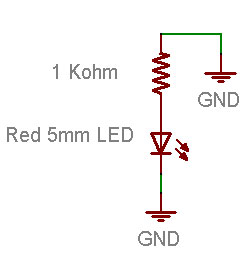
Chúng tôi sẽ thực hiện một thay đổi rất nhỏ mạch dây lên của chúng tôi
Trong sơ đồ mới của chúng tôi, thay vì kết nối các điện trở điện V 5, chúng tôi sẽ kết nối nó với mặt đất.
Trước khi bạn thay đổi breadboard của bạn, làm cho một đoán của những gì sẽ xảy ra:
- Giá LED thắp sáng?
- LED sẽ đi ra ngoài?
- Cái gì khác?
Bây giờ làm cho sự thay đổi để breadboard của bạn:
Bạn sẽ nhận thấy rằng, trên thực tế, đèn LED đã đi ra ngoài. Đó là bởi vì nó không còn kết nối với một nguồn năng lượng và hiện tại không chảy. Bằng cách kết nối điện trở đến 5 V hoặc mặt đất, bạn có thể bật đèn LED trên và tắt. Nếu bạn rất nhanh, bạn có thể làm cho nháy LED!
Hmm ....
Lại đến thăm một người bạn cũ
Khởi động phần mềm Arduino một lần nữa và mở ra các ký họa MyBlink từ bài học 2. Nếu bạn còn lại nó với thời gian chậm trễ của 10ms, bạn có thể muốn thay đổi nó để lại của nó tới 500ms và off 500ms. Tải lên các ký họa Arduino của bạn. Bây giờ thay đổi dây breadboard của bạn để nó phù hợp này sơ đồ mạch.
Bạn sẽ thấy lần lượt LED và tắt. Nếu bạn có một Arduino Diecimila, cả hai đèn LED trên bo mạch chủ và LED có dây sẽ nhấp nháy trong unison. Cho phép xem mã đó một lần nữa
void loop()                     // run over and over again
{
  digitalWrite(ledPin, HIGH);   // sets the LED on
  delay(500);                  // waits for a second
  digitalWrite(ledPin, LOW);    // sets the LED off
  delay(500);                  // waits for a second
}
Đây là một khả năng khá tuyệt vời và là cơ sở của tất cả các thiết bị điện tử! Bạn có thể muốn suy nghĩ về nó mát mẻ như thế nào cho một vài khoảnh khắc.
Một pin mới
Bây giờ thay đổi hệ thống dây điện để điện trở được kết nối pin ổ cắm # 12
Đèn LED không nhấp nháy nữa! Cho phép sửa chữa nó!
Quay trở lại đầu ký họa và tìm dòng này một lần nữan
int ledPin = 13; // LED connected to digital pin 13
int ledPin = 12; // LED connected to digital pin 12 now!
Các bài tập!
Dành thời gian thử nghiệm với các chân khác nhau. Kết nối LED ổ cắm pin khác nhau, và sửa đổi các ký họa để các đèn LED sẽ nhấp nháy.
Thay đổi trên hệ thống dây điện của bạn để nó phù hợp này sơ đồ mạch:
Hãy chắc chắn để sửa đổi bạn phác thảo để ledPin là 13 một lần nữa. Lập lại và tải nó lên Arduino. Đèn LED làm gì?
Đánh dấu văn bản dưới đây để xem câu trả lời
Nó nhấp nháy cũng giống như trước đây
Nếu bạn có 1 Arduino Diecimila, bạn nhận thấy về breadboard LED và các on-board LED?
Đánh dấu văn bản dưới đây để xem câu trả lời
Chúng được xen kẽ trong khi họ nhấp nháy
Tại sao bạn nghĩ rằng đó là?
Đánh dấu văn bản dưới đây để xem câu trả lời
Khi pin là LOW (kết nối với mặt đất) breadboard LED là: hiện nay đang chảy từ +5 V với mặt đất thông qua pin. Khi pin là HIGH (kết nối với +5 V) LED on-board, giống như trước đây.
Thêm một đèn LED màu xanh ...
OK chắc chắn rằng bạn đã có rất nhiều thực hành rối tung xung quanh với đèn LED. Đó là thời gian để đi đầy đủ màu sắc! Tìm đỏ, màu xanh lá cây và màu xanh LED. Nếu bạn có Arduino đề Pack họ sẽ là ba LEDs rõ ràng. Bạn không thể nói đó là một trong cho đến khi họ được thắp sáng vì vậy chỉ cần xây dựng các mạch và sau đó sắp xếp lại chúng nếu cần thiết.
int redPin = 12;                  // Red LED connected to digital pin 12
int greenPin = 11;                // Green LED connected to digital pin 11

void setup()                      // run once, when the sketch starts
{
  pinMode(redPin, OUTPUT);        // sets the digital pin as output
  pinMode(greenPin, OUTPUT);      // sets the digital pin as output
}

void loop()                       // run over and over again
{
  digitalWrite(redPin, HIGH);     // sets the Red LED on
  digitalWrite(greenPin, HIGH);   // sets the Green LED on
  delay(500);                     // waits for half a second
  digitalWrite(redPin, LOW);      // sets the Red LED off
  digitalWrite(greenPin, LOW);    // sets the Green LED off
  delay(500);                     // waits for half a second
}
Bạn chỉ có thể sao chép và dán văn bản này vào cửa sổ của phần mềm Arduino.
Nhanh chóng đố
Bản phác thảo này làm gì? Biên dịch và tải lên các bản phác thảo để kiểm tra giả thuyết của bạn.
Đánh dấu văn bản dưới đây để xem câu trả lời
Nó nhấp nháy hai đèn LED kết nối với chân 11 và 12 cùng một lúc
3434343434
Nếu bạn gặp vấn đề nhận được bản phác thảo này để làm việc, kiểm tra:
Phác thảo biên soạn đúng cách? Nó tải lên chính xác?
Các đèn LED trong đúng cách?
Điện trở trong ổ cắm phải không?
Các đèn LED kết nối với mặt đất ở phía bên kia?
Breadboard có dây lên bên phải? Kiểm tra kết nối của bạn.
Các bài tập!
Thay đổi mã để các đèn LED luân phiên nhấp nháy của họ:
3535353535
Đánh dấu văn bản dưới đây để xem một trong những giải pháp có thể
Thay đổi các digitalWrite thứ hai () gọi thủ tục để thiết lập các pin LOW, và cuộc gọi thứ tư để thiết lập các pin cao.
Thay đổi vòng lặp () mã thủ tục để cả hai đèn LED là 500 ms, sau đó chỉ có đèn LED màu đỏ cho 500 ms, sau đó cả hai đèn LED, và cuối cùng chỉ có đèn LED màu xanh lá cây cho 500 ms
Đánh dấu văn bản dưới đây để thấy một câu trả lời
void vòng lặp () / / chạy qua và hơn nữa
{
digitalWrite (redPin, CAO); / / bộ Red LED
digitalWrite (greenPin, CAO); / / bộ Green LED trên
sự chậm trễ (500); / / chờ đợi cho một nửa thứ hai
digitalWrite (redPin, CAO); / / bộ Red LED
digitalWrite (greenPin, LOW); / / thiết lập Green LED off
sự chậm trễ (500); / / chờ đợi cho một nửa thứ hai
digitalWrite (redPin, LOW); / / thiết lập các Red LED off
digitalWrite (greenPin, LOW); / / thiết lập Green LED off
sự chậm trễ (500); / / chờ đợi cho một nửa thứ hai
digitalWrite (redPin, LOW); / / thiết lập các Red LED off
digitalWrite (greenPin, CAO); / / bộ Green LED trên
sự chậm trễ (500); / / chờ đợi cho một nửa thứ hai
}
Cuộc phiêu lưu màu sắc đầy đủ!
Sau khi thành công thêm hỗ trợ cho màu xanh lá cây đèn LED thời gian của mình để thêm màu xanh LED.
Đi trở lại bản phác thảo này, một trong những bước cuối cùng
int redPin = 12; / / Red LED kết nối kỹ thuật số pin 12
int greenPin = 11; / / Green LED kết nối kỹ thuật số pin 11
void setup () / / chạy một lần, khi bắt đầu ký họa
{
pinMode (redPin, OUTPUT); / / bộ pin kỹ thuật số như đầu ra
pinMode (greenPin, OUTPUT); / / bộ pin kỹ thuật số như đầu ra
}
void vòng lặp () / / chạy qua và hơn nữa
{
digitalWrite (redPin, CAO); / / bộ Red LED
digitalWrite (greenPin, CAO); / / bộ Green LED trên
sự chậm trễ (500); / / chờ đợi cho một nửa thứ hai
digitalWrite (redPin, LOW); / / thiết lập các Red LED off
digitalWrite (greenPin, LOW); / / thiết lập Green LED off
sự chậm trễ (500); / / chờ đợi cho một nửa thứ hai
}
Bạn chỉ có thể sao chép và dán văn bản này vào cửa sổ của phần mềm Arduino.
Bây giờ bạn sẽ thêm các mã Blue LED của chính mình
Bước 1. Thêm dòng mã sẽ tạo ra một bluePin gọi là biến. Pin nó phải được chỉ định? Kiểm tra sơ đồ trên để tìm hiểu.
Bước 2. Thêm dòng mã mà sẽ cho biết Arduino bluePin là một đầu ra kỹ thuật số.
Bước 3. Thêm 2 dòng mã để các đèn LED màu xanh sẽ được thắp sáng khi đèn LED màu đỏ và màu xanh lá cây được thắp sáng
Biên dịch và xác minh mã của bạn. Liệu nó có làm việc? Nếu không sử dụng các kỹ năng gỡ lỗi của bạn để tìm ra những gì là sai và sửa chữa nó!
Màu sắc pha trộn
Bây giờ bạn có ánh sáng đỏ, xanh lá cây và màu xanh, bạn có thể bắt đầu có vui vẻ với màu sắc pha trộn. Màu trộn là khả năng gọn rằng mắt của chúng tôi phải kết hợp các màu sắc ánh sáng khác nhau và tạo ra một màu mới
3636363636
Một phụ (ánh sáng) màu sắc pha trộn sơ đồ
Theo sơ đồ này, nếu chúng ta có cả ánh sáng màu đỏ và màu xanh pha trộn với nhau, chúng ta sẽ nhận được một ánh sáng tím.
Nhanh chóng đố
Sửa đổi mã của bạn để tạo ra ánh sáng màu sau đây: Violet (màu đỏ và màu xanh), Turquoise (màu xanh - màu xanh lá cây) và màu vàng (màu xanh lá cây và đỏ)
Bây giờ bạn đã sẵn sàng cho "dự án cuối cùng" của bài học này rất dài. Bạn sẽ làm cho một ánh sáng màu sắc thay đổi!
Sửa đổi các ký họa để ánh sáng phát ra đi theo thứ tự: đỏ, vàng, xanh lá cây, turquioise, tím màu xanh và màu đỏ. Nó nên tạm dừng một lần thứ hai giữa mỗi thay đổi màu sắc.
Gợi ý: Một cách để làm cho công việc trộn màu tốt hơn là để khuếch tán ánh sáng, trong một hộp ánh sáng. Bạn có thể làm cho một hộp ánh sáng trong số giấy thường, kéo và một số băng. Chỉ cần làm một hộp giấy và cắt một lỗ trong đó. Điền vào các hộp khăn giấy. Mô hoạt động như khuếch tán, giúp kết hợp ánh sáng độc đáo
3737373737
3838383838
3939393939
No comments:
Post a Comment